Welcome to KZY Electronic Technology Co., Ltd
Tel: +86 18617158103
Email: sales@###.com
Working principle:
Fingerprint processing includes two processes: fingerprint registration process and fingerprint matching process (fingerprint matching which is divided into fingerprint matching (1: 1) and fingerprint search (1: N) in two ways].
When the fingerprint is registered, entry twice for each fingerprint, and processed the image, composite template is stored in the module. Fingerprint matching, through the fingerprint sensor, entry the fingerprint image and processing, and then matching comparison with the module fingerprint template (if it is matched a template specified in the module, known as fingerprint matching, that is 1: 1 mode. If it is matched with multiple templates, it is called fingerprint search mode (1: N mode). The module gives the result of matching (pass or fail).
Feature:
Profile: 256 bytes
Template file: 512 bytes
Power supply voltage: DC 5V
Operating current: <120mA
P eak current: <130mA
Fingerprint image input time: <0.5 seconds
Window area: 18.5 mm x 14.6 mm
Matching mode (1: 1)
Search method (1: N)
Storage capacity: 200 pieces
Security level: Five (from low to high: 1,2,3,4,5) system default 3
FAR: <0.001% (security level is 3)
Rejection rate (FRR): <1.0% (security level 3)
Search time: <1.0 seconds (1: 500 average)
Resolution: 500ppi
Host computer interface: UART (TTL logic level)
Communication baud rate (UART): (9600XN) bps Where N = 1 ~ 6 (default value N = 6, namely 57600bps)
Temperature: -25 °C to +55 °C
Relative humidity: 40% RH-85% RH (no condensation)
Storage temperature: -40 °C to +85 °C
Relative humidity: <90% H (no condensation)
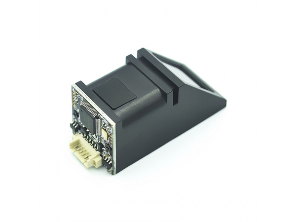
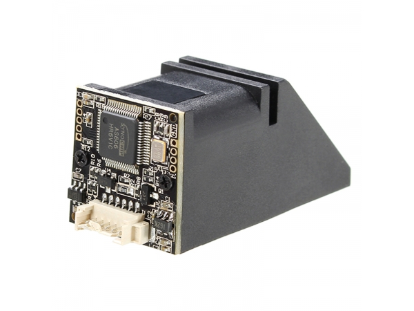
Optical module (C3) overall dimensions (L × W × H): 47.65mm x 20.50mm x 21.20mm
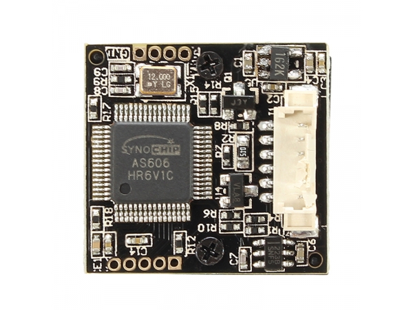
Capacitive module dimensions: Main control board (L × W × H): 35mm x 28mm x 7mm
Sensors (L × W): 33.4mm x 20.4mm
Scratch-type module dimensions: Main control board (L × W × H): 35mm x 28mm x 7mm
Sensor board (L × W × H): 24mm x 20mm x 5mm
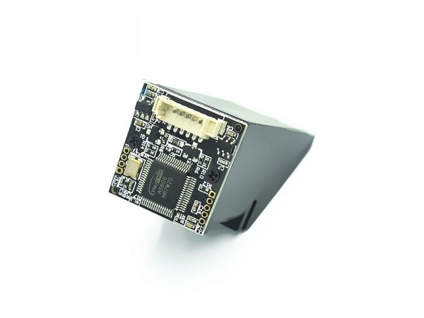
Host computer interface, the pins are defined as follows:
|
Num. |
Pin Description |
Remarks |
|
1 |
Finger detection power + |
3.6-5V |
|
2 |
Finger detection signal output |
The standard output is active high |
|
3 |
Power supply + |
Power + 5V |
|
4 |
Transmit |
TX |
|
5 |
Receive |
RX |
|
6 |
Power supply - |
Power - |
Module requires 2 groups of power supply, a group for serial power supply, a group for power chip power, common ground.
1,6 for the sensor chip power supply, need to be power all the time; 3,6 for the module serial power supply. When the finger near the fingerprint window, pin 2 produces a high level, when MCU receive this level, through the module serial power control circuit (transistor or MOS tube) power the module 3,4 feet.
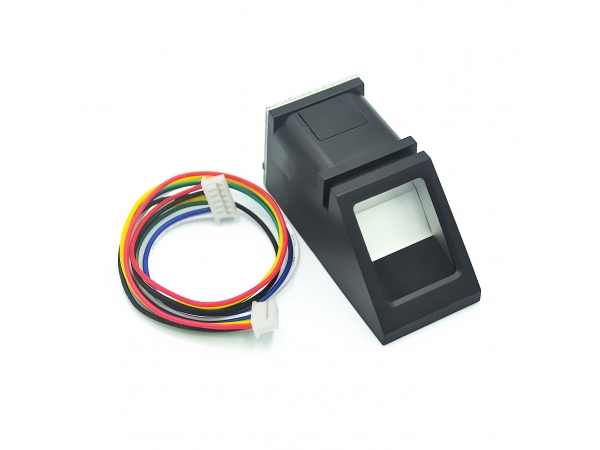
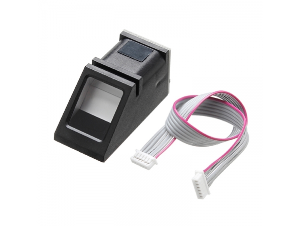
Module and the user equipment serial communication, the interface J1 pin is defined as follows:
|
Pin number |
Name |
Type |
Function |
|
1 |
+3.3V_ON |
IN |
Finger detection power supply positive input |
|
2 |
T OUCH |
OUT |
Finger detection signal output terminal |
|
3 |
VUSB |
IN |
Positive power input. (Line color: red) |
|
4 |
TX |
OUT |
Serial data output. TTL logic level. (Line color: green) |
|
5 |
RX |
IN |
Serial data input. TTL logic level. (Line color: white) |
|
6 |
GND |
- |
Signal ground. Connected internally to the power ground. (Line color: black) |
Note: In the Type field, IN means input to the module and OUT means output from the module.
Hardware connection:
Module through the serial communication interface, can be used directly with the 3.3V or 5V microcontroller to communicate: Module data transmission pin (4-pin TX) connected to the host computer data receiver (RXD), module data receiving pin (5 feet RX) connect on the position machine data transmission terminal (TXD).
To communicate with the host computer of the RS-232 level (eg PC), please add a level-shifting circuit between the module and the host computer (eg MAX232 circuit).
Serial protocol:
Using half-duplex asynchronous serial communication. The default baud rate is 57600bps and can be set to 9600 ~ 115200bps by command.
The transmitted frame format is 10 bits, a 0-level start bit, 8-bit data (LSB first) and a stop bit without parity bit.
Power-up delay time:
After the module is powered on, it takes about 200mS to initialize. During this time, the module can not respond to the host command.
Electrical parameters (all levels referenced to power / ground GND):
1. Power input:
|
Item |
Parameter |
Unit |
Remarks |
|||||||||||||
|
Min |
Typical |
Max |
||||||||||||||
|
Supply voltage (Vin) |
3.8 |
5 |
6 |
V |
Normal operating value |
|||||||||||
|
Limit voltage (Vinmax) |
-0.3 |
|
6 |
V |
Exceeding this range may |
|||||||||||
|
Operating current (Icc) |
90 |
100 |
110 |
mA |
|
|||||||||||
Related products
Copyright 2022 KZY Electronic Technology Co., Ltd All Rights Reserved
Web Design—Quanfang Network
| ||||||||||||||||


 123456