7.Weight:58g
Feature:
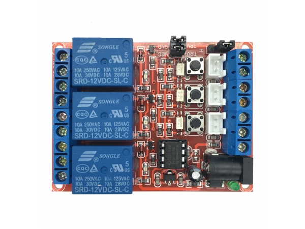
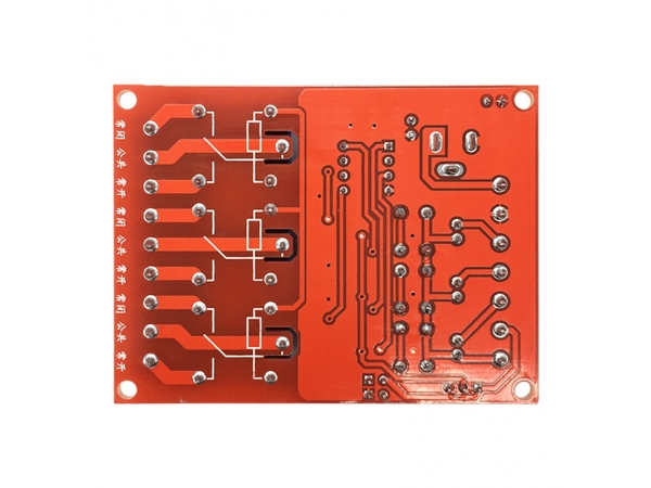
1.Double sided plate design PCB, 3 channel independent design, without interference
2.The design of single chip microcomputer, stable and reliable performance, strong anti-interference, no error triggering, superior performance
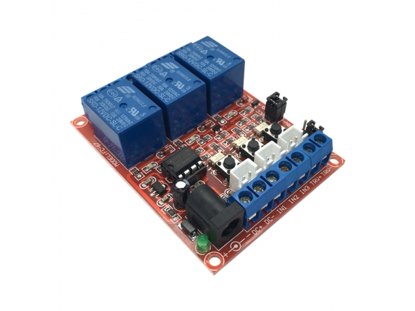
3.Interface design user-friendly, with a good terminal, can be directly connected to the lead
4.The trigger end has optocoupler isolation, the trigger power supply can be independently connected with the power supply, and the system can be completely isolated
5.With 3 tact switches for product testing, the stability of the product is checked directly
6.Have power indicator (green LED) and 3 switch instructions (red LED)
7.The design has 4 bolt holes: the distance is 67.5*50mm, and the aperture is 3.1mm
Power input:
1.DC+: the module supplies the positive pole to the same voltage as the relay
2.DC-: module power negative
Trigger terminal:
1. IN1-IN3: corresponds to the 1-3 channel relay to trigger the control terminal, which supports high or low level trigger
2.TRV+: external trigger power positive, such as external trigger power, RTV+ and VCC between the jumper to be removed
3.TRV-: external trigger power negative, such as external trigger power, RTV- and GND between the jumper to be removed
4.3 micro switches: corresponding to the 1-3 relay test button, the low level trigger is effective
5.White terminal block: corresponding to 1-3 way relay external switch control end, low level trigger is effective;
6.High / low level trigger selection. When the COM is connected to the L, the low level trigger is valid. When the COM is connected with the H terminal, the high level trigger is effective
7.NO1 - NO3: the relay normally opens the interface, the relay is left before attracting, and then short connected with the COM after attracting
8.COM1 - COM3: relay common interface
9.NC1 - NC3: relay normally closed interface, before the relay is pulled in, short connection with COM, hang in the air after attracting


 123456